#Ironcad circles not smooth update#
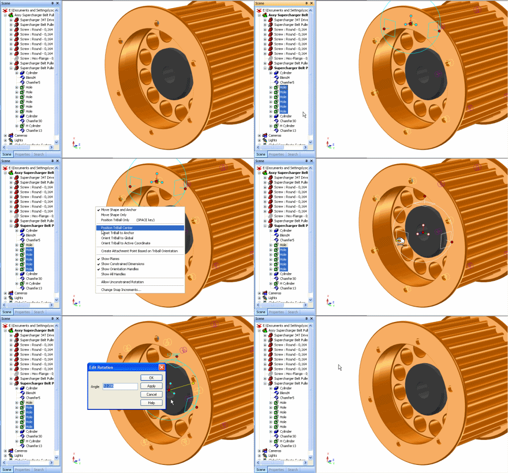
When the edge changes direction, the pattern will update to reflect the new direction). Select a linear part edge or axis to define the direction of the pattern (Note: The pattern direction is defined by this edge selection.If a part is not selected, a request will appear to select a part to apply the command to. Select the Pattern Feature command from the Feature Fluent Ribbon Bar.Select a part in the scene to apply the pattern (or skip to step #2).To edit patterns, right-click on the pattern feature in the scene or scene browser and select Edit Definition.

When the pattern result feature is selected, the entire feature will be highlighted yellow, denoting the pattern. It is not possible to edit the feature definition of the pattern result features directly. This means that changes to the original parent feature will modify the results of the pattern. The pattern feature result is a true parent-child relationship. When a Pattern Feature is generated, parameters are automatically added to the parameter table to parametrically control the pattern results. The pattern is based on a new algorithm that provides fast updates when the geometry is modified and benefits users with many feature patterns. The reference is maintained when the geometry is modified in which the pattern will update to reflect the change in the reference modification. The pattern feature is an feature that allows the user to refer to an edge/vector to define the direction, axis, or path in Linear, Bilinear, circular, edge, and sketch path patterns. Pattern Feature Command - The pattern feature command provides performance improvements, direction reference relations, pattern of pattern, supports blend/chamfer/draft in the pattern result, and supports the feature extrude to operations (For Example - Extrude to Surface can be maintained in the patterned features). It supports linear, circular, and bilinear patterns, however it is only a single feature pattern (no support for pattern of pattern). Additionally this pattern is using the feature linking capability. This pattern only controls the number, distance, and location. TriBall Pattern - The existing TriBall pattern is a quick method to create a parametric pattern using the positioning power of the TriBall. There are two different types of patterns, each providing a unique value. IMHO the best solution is to create your own Shape implementation and use it to create a ShapeDrawable.īelow is a simple implementation of rounded rectangle, that will allow you to inset it's border.Creating patterns of features is a common task in design. I've encountered this problem recently and came up with a different solution. Here is a screen shot of the result of the above code: Then use the layerDrawable as your background. tLayerInset(0, halfStrokeWidth, halfStrokeWidth, halfStrokeWidth, halfStrokeWidth) Int halfStrokeWidth = (int)(strokeWidth/2)

LayerDrawable layerDrawable = new LayerDrawable(layers) ShapeDrawable.getPaint().setPathEffect(new CornerPathEffect(10)) ShapeDrawable.getPaint().setStrokeWidth(strokeWidth) ShapeDrawable.getPaint().setAntiAlias(true) ShapeDrawable.getPaint().setStyle(Style.STROKE) ShapeDrawable.getPaint().setColor(Color.parseColor("#5a2705")) ShapeDrawable shapeDrawable = new ShapeDrawable(new RectShape()) Solution: Use a layer list to inset the rectangle by the amount that is being clipped (half the stroke width), like this: float strokeWidth = 2 This effect will be much more apparent if you try a bigger stroke and radius such as 10 and 40, respectively.Įither use an XML drawable, which doesn't seem to have this problem, like in Harshit Jain's answer, or do the following if you must (or prefer to) use a programmatic solution. Look closely at your image and you'll see that your stroke is only 1 pixel wide, even though you requested 2. Using a programmatically-created shape drawable as a View background results in the outer half of your stroke width getting cropped off (for reasons I don't know).


 0 kommentar(er)
